
How to Configure VLANs – Example (HTTP and CLI) DGS-1510-Series
Example Setup:

• VLAN configuration
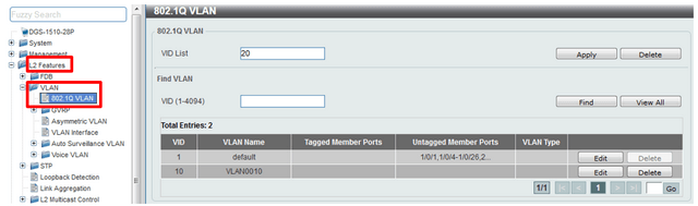
Step 1 - Create the vlan
Add the id vlan and click “Apply” - L2 Features > VLAN > 802.1Q VLAN
CLI commands:
vlan 10
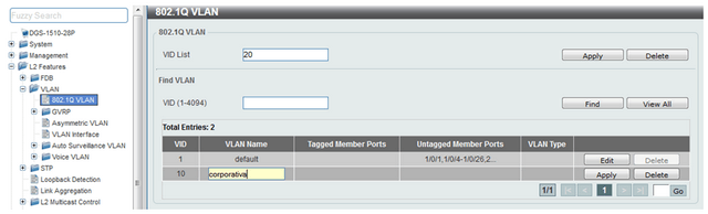
Step 2 - Edit the name
VLAN Name: corporative
Click “Edit” and change the name of the VLAN in the VLAN Name column, once changed the name pique at the end of the line Apply.
CLI commands:
vlan 10
name corporative
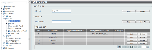
CLI commands:
vlan 20
name guests
exit
vlan 30
name router
exit
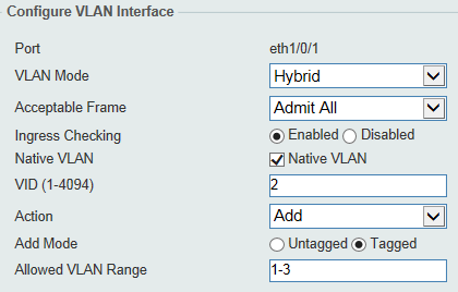
Step 3 - Configuring Ports
We have 3 types of ports - L2 Features > VLAN > VLAN Interface
• Hybrid
• Access
• Trunk
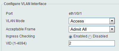
Example: Hybrid mode:
- A Vlan untagged (Native)
- Multiple Tagged vlan
(VID 2 untagged, ID 1 and 3 Tagged)
CLI commands:
configure terminal
interface ethernet 1/0/1
switchport hybrid native vlan 2
switchport hybrid allowed vlan tagged 1-3
end
Example: Access mode VLAN2 (untagged)
CLI commands:
interface ethernet 1/0/1
switchport mode access
switchport access vlan 2
acceptable-frame admit-all
end
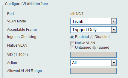
Example: Trunk port
Only allow tagged vlans
CLI commands:
configure terminal
interface ethernet 1/0/1
switchport mode trunk
switchport trunk native vlan tag
acceptable-frame tagged-only
end
Step 3.1- Corporate VLAN
5-16 ports of each unit, where users will connect using the Access mode.
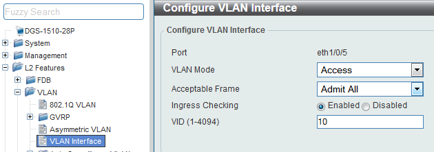
CLI commands:
configure terminal
interface range ethernet 1/0/5-1/0/16
switchport mode access
switchport access vlan 10
acceptable-frame admit-all
end
configure terminal
interface range ethernet 2/0/5-2/0/16
switchport mode access
switchport access vlan 10
acceptable-frame admit-all
end
Step 3.2 - Guest VLAN
In ports 17-22 of each unit, where guests can connect using the Access mode.
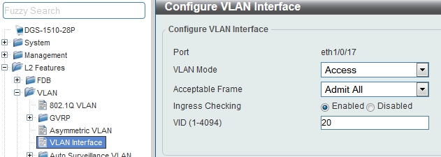
CLI commands:
configure terminal
interface range ethernet 1/0/17-1/0/22
switchport mode access
switchport access vlan 20
acceptable-frame admit-all
end
configure terminal
interface range ethernet 2/0/17-2/0/22
switchport mode access
switchport access vlan 20
acceptable-frame admit-all
end
Step 3.3 - VLAN for router
Port 24 is where a router will be connected
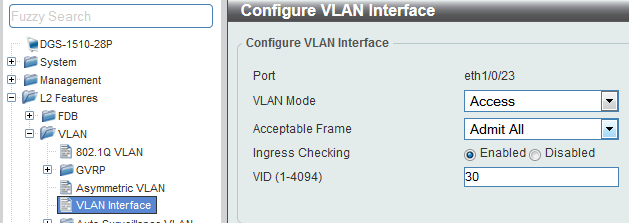
CLI commands:
configure terminal
interface range ethernet 1/0/23-1/0/24
switchport mode access
switchport access vlan 30
acceptable-frame admit-all
end
configure terminal
interface range ethernet 2/0/23-2/0/24
switchport mode access
switchport access vlan 30
acceptable-frame admit-all
end
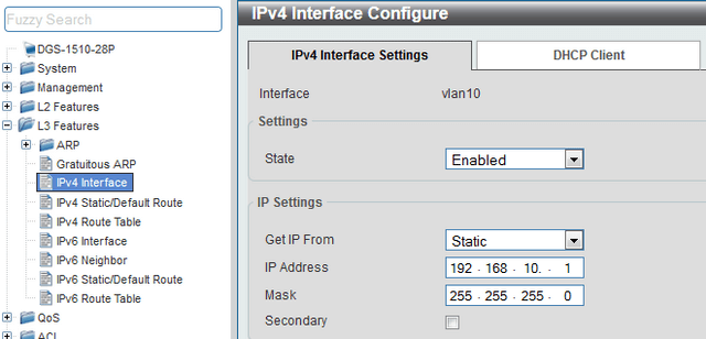
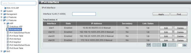
Step 4 - Configuring IP interfaces for each VLAN - L3 Features > IPv4 Interface
Enter in IPv4 interface, enter the corresponding VLAN ID in the box "VLAN Interface" and pique Apply, then pique Edit to configure the IP interface and pique Apply to confirm the settings.
CLI commands:
interface vlan 10
ip address 192.168.10.1 255.255.255.0
exit
CLI commands:
interface vlan 20
ip address 192.168.20.1 255.255.255.0
exit

CLI commands:
interface vlan 30
ip address 172.16.0.1 255.255.255.0
exit

Step 5 - Create a Static Route
We will create a default route to the router that provides internet connection through VLAN30
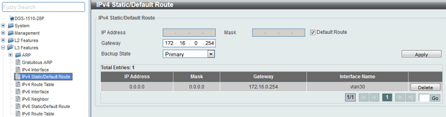
CLI commands:
configure terminal
ip route 0.0.0.0 0.0.0.0 172.16.0.254 primary
end
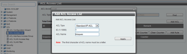
Step 6 - Create ACLs to block access from “Guest” network to the “Corporate” network.
Enter the ACL > ACL Access List option, select the ALL Type ACL option and click the “Add” ACL to create an ACL for IP Standard (basic) type and thus deny access network 192.168.20.0/24 to 192.168. 10.0 /24
Remember that rules are executed sequentially.
CLI commands:
ip access-list block 1
Once the rule is created, close the window (Add ACL Access List) and then edit the rule created by clicking “Edit”, in the access list to add the two necessary rules clicking on “Add Rule”
CLI :commands
interface range ethernet 1/0/5-1/0/16
ip access-group bloqueo in
exit
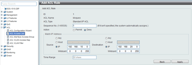
Add the inverse rule

CLI commands:
ip access-list block 1
1 deny 192.168.10.0 0.0.0.255 192.168.20.0 0.0.0.255
2 deny 192.168.20.0 0.0.0.255 192.168.10.0 0.0.0.255
exit
Step 7 - Assign ACLs to the ports involved
Enter ACL > ACL Access Interface Group and associate the name of the ACL created to the appropriate port
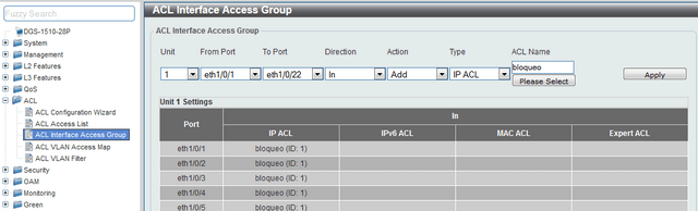
CLI Commands:
interface range ethernet 1/0/5-1/0/16
ip access-group bloqueo in
exit
These may also help:
- How to Prevent ARP Spoofing - DGS-1210-Series Read Answer
- How to configure Voice VLAN on my DGS-1210 Read Answer
- How to Protection against malicious virus or worm attacks – DGS-1210-Series Read Answer
- How to Setup Security with DHCP Server Screening – DGS-1210-Series Read Answer
- How to Setup Virtual Stacking (SIM) - DGS-1500-Series Read Answer
- How to Configure Auto Surveillance VLAN – DGS-1210 Series Read Answer